Radio receiver is dedicated to entertain and acknowledge human mind. Mechanism of radio transmit ion involves generating audio frequency current, modulation or mixing of this audio frequency with radio frequency, because audio frequency current alone can travel only 332kms in atmosphere. Moreover modulated signal travels in 3 lakh km/sec the speed of light.
In radio receiver modulated signal is separated into audio and carrier signal in detector stage, which is then amplified and fed to the speaker.
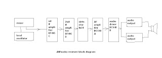
Intermediate frequency transformers receive all the frequencies, filter the desired frequency and take it to the audio stage. It functions between audio stage and oscillator stage so it’s called intermediate. It’s aligned at 455kilocycles to receive all frequencies. There are three IFTs, white-the detector, green-the inter, and yellow-the oscillator.
Printed circuit board for AM radio is generally ‘L’ shaped

To make our band work we need two types of coils. To receive signals3pined antenna coil is engaged. To separate the required channel5pinned oscillator coil is engaged which works hand in hand with the gang. There will be two antenna coils and two oscillator coils for a two band radio.
Medium wave antenna coil is fixed over ferrite rode. Band switch connections are made such that it connects on both the sides of three poles of the band switch.
While assembling the ‘L’board output stage is assembled first. Driver transformer is checked for continuity in primary coils and the secondary as well as it s checked for shortage. After the transformer being fioxedAC188s are soldered, resistors and capacitor come s in their way. This ultimately completes the output stage.

Next step is to complete the voltage amplifier stage.BC548 is the voltage amplifier transistor. Another amplifier is BC548A.Both of them is connected accoding to the circuit diagram .After the completion of audio stage it is tested for output.
Audio stage assembly is followed by IFT stage .Oscillator coils and antennae coils are connected accordingly. Whole chassis of radio works as negative pole. Short wave antenna coil require a loop antennae.Radio is powered using a 6volt eliminator. Switched on ..tuned… Fat..Fat…Frrr….rrrrr…………Akashavani ..Kozhikode.Our radio gadget is ready to entertain.


AM radio PCB
ReplyDeletesir, can u tell me the adjustments of the 3 IFT coils for a not working radio to service it.
ReplyDeleteThe Schematic is from MS Radio institute Thiruvananthapuram :-)
ReplyDeleteYears back i made my first radio following the instructions given in that book. Its bringing back those memories when i saw that circuit. .. ...
yes,are you from tvm,thanks for your comment!!
DeleteOh! L-Plate Radio i even made I-Plate also when i was Young in 1980 ;)
ReplyDeleteFrom where can I get this l-board,
ReplyDeleteIt was my first learning board and I am searching one board to teach my son,
My very old memories raised again.
Thanks dude.
From where can I get this l-board,
ReplyDeleteIt was my first learning board and I am searching one board to teach my son,
My very old memories raised again.
Thanks dude.
I TOO DESIGNED THE SAME CIRCUIT WHEN I DID MY DIPLOMA
ReplyDeleteTHANKS FOR SHARING THE CIRCUIT ...
In 1990s I have brought many L board radio kits from Devices, Pallimuku,EKM and assembled it for those interested.
ReplyDeleteIndeed l board radio kits Please give your contact
Deletei need L PCb and audio transformer. if you have spare please give me, i will pay for this, VU3KVB, Saravanan, 9840369677, prohithar@gmail.com
ReplyDelete